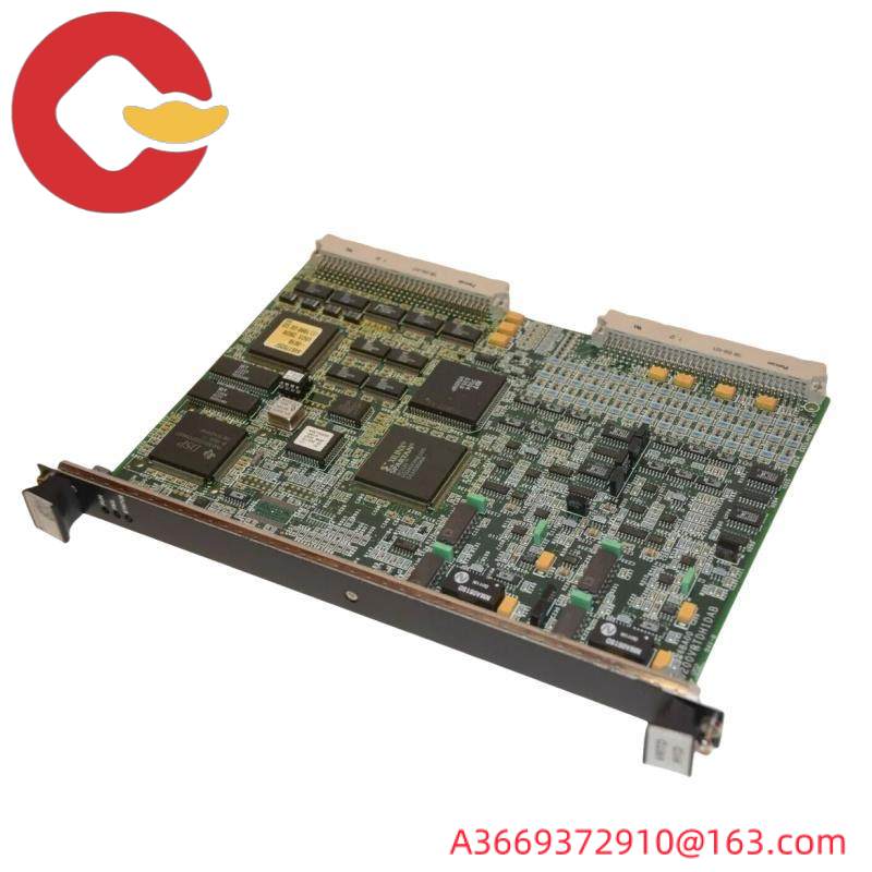
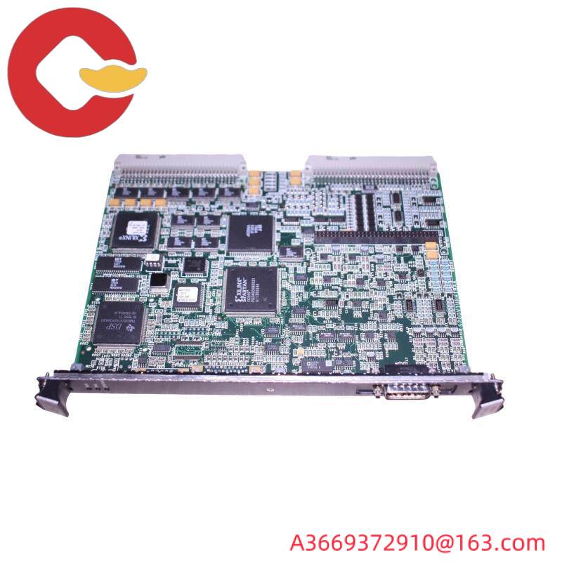
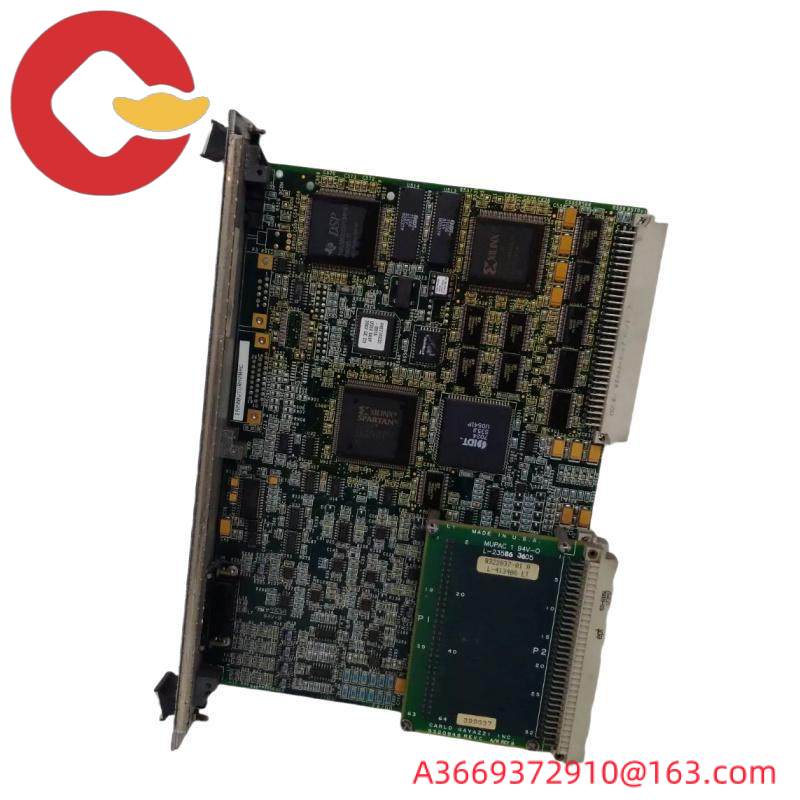
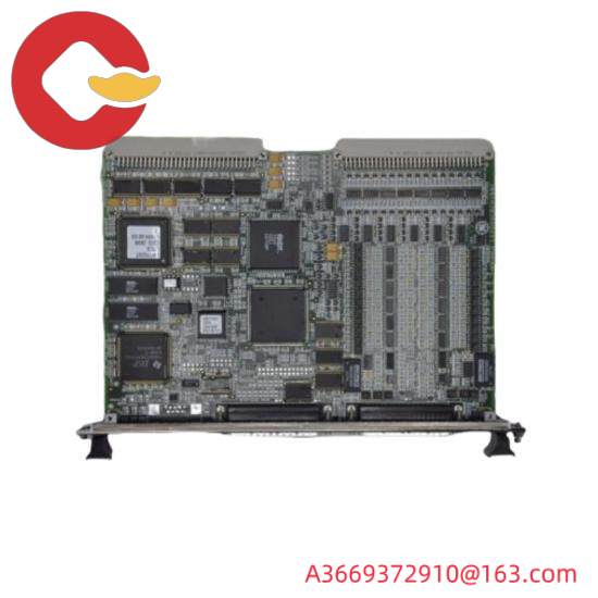
IS200VCRCH1BBC Mark VI printed circuit board
The IS200VCRCH1B is a GE Mark VI board component. The MKVI is part of the Speedtronic family of gas turbine and steam turbine management systems that GE has been developing and improving since the release of the Mark I in the 1960s. The MKVI is the fifth management system in the Speedtronic series, featuring triple redundant control over all protection parameters and critical controls, as well as advanced control mechanisms for protecting and monitoring turbine systems.
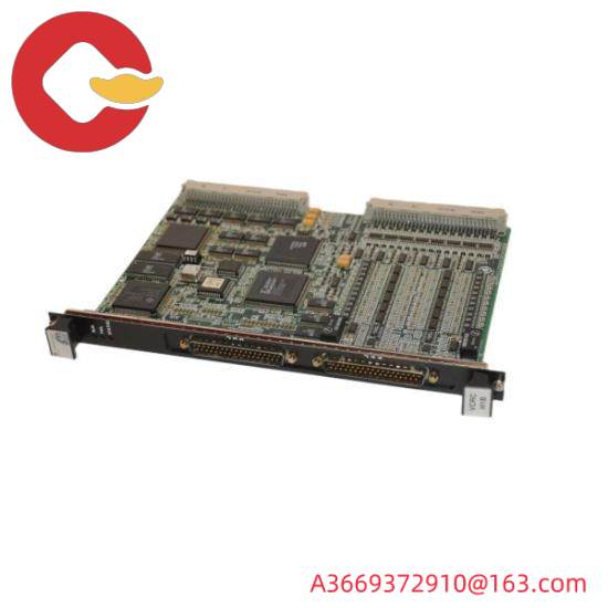
The IS200VCRCH1B is used as a discrete input/output board. It is a single-slot board that has the same features as the VCCC board, but does not include a subboard, so it takes up less rack space. However, since the relay output of this board uses the J3/J4 port on the VME rack, the cable must be placed on the front panel. If you do not wish to do so, use a VCCC board instead of a VCRC PCB.
The IS200VCRCH1B has a front panel with two cable connectors (J33 and J44). The panel also contains three LED components, which are located near the top corner of the board. These leds are green, red, and orange, and are labeled Run, Failure, and Status.
The IS200VCRCH1B is surface-filled with two backplane connectors. Multiple conductive connectors are located on the board surface (P4 to P6). The board also includes resistors, diodes, capacitors and TP test points. The board has more than 30 transistors and 2 power supplies. Integrated circuits located on the surface of the board include FPgas and various SRAM and RAM chips. For more information about the IS200VCRCH1B, please refer to the data sheet, manual or Mark VI Control System Guide.
Why do turbines need monitoring and speed control?
In the heat generated in an atomic power station, nuclear fusion, water is heated and produces steam to power turbines. Self-holding frequency F, must maintain a constant speed of 1500 RPM. Home Settings are affected by frequency changes.
What printed circuit board can PCB?
A printed circuit board or PCB is a device that uses conductive paths, wires, or signal wires etched from copper sheets to be laminated onto a non-conductive substrate to mechanically support and electrically connect electronic components.
What is the analog output module in PLC?
PLC Analog output PLC outputs, which are widely used in industrial applications to operate actuators, valves, and motors, using typical analog output ranges such as 5 V, 10 V, 0 V to 5 V, 0 V to 10 V, 4 to 20 mA, or 0 to 20 mA.
Where to buy printed circuit boards?
In our store, we offer a variety of printed circuit boards. If you have any questions, please contact us and our team will be happy to assist you.